
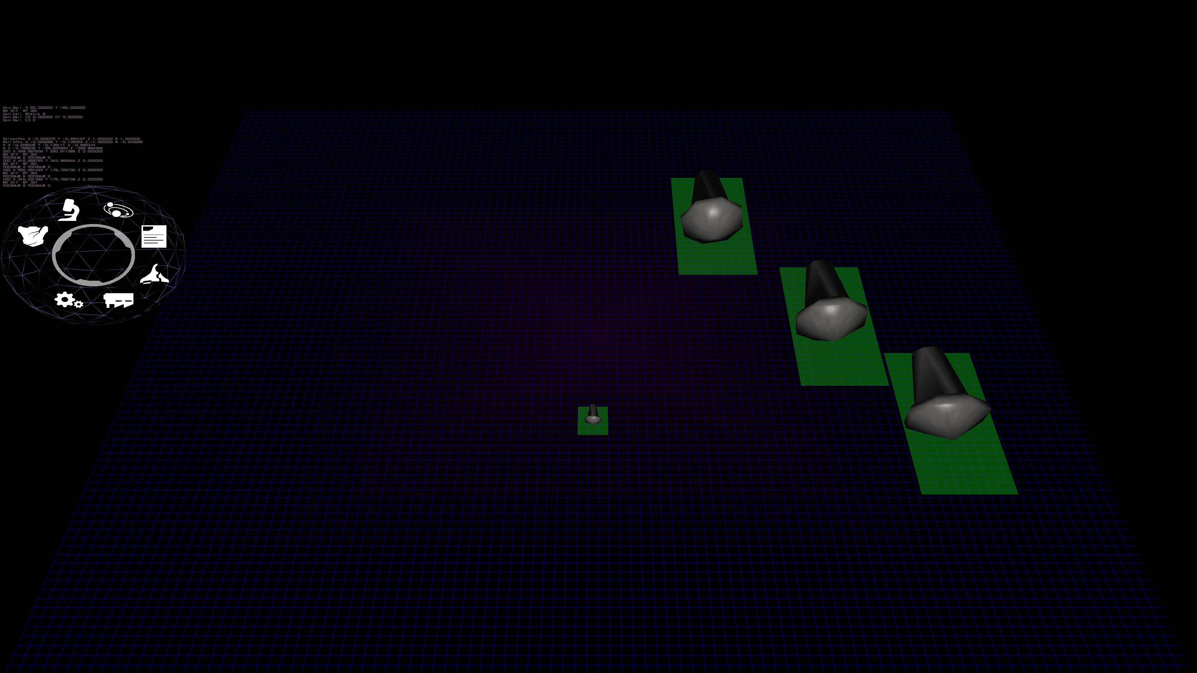
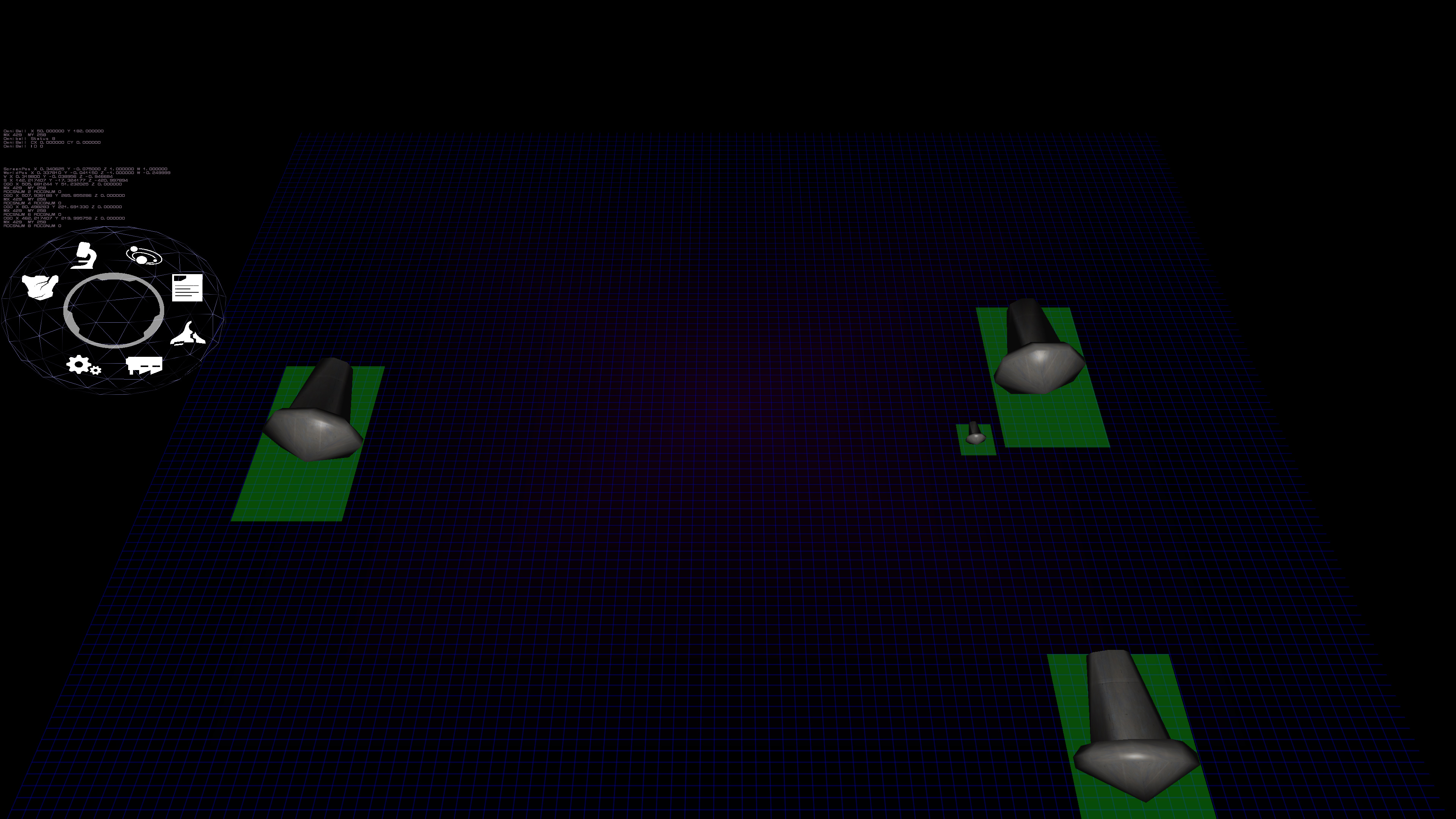
First look at new UI control
While not that pretty yet, the functionality is almost there. In the screen caps shown here, you can see the pretty Omniball on the left, but the main interest here is the new "grid" control. This grid control, once fully completed, will not only work to allow items to be placed on a grid, but also end up serving as scrollable pick lists of objects. The idea here is that you will be able to select an object, and drag it to another grid control, and insert that object. Sounds boring, but think of having a pick list of all these different weapons. You can simply with a flick, move through all the available weapons, with the scrolling automatically keep going like on your smart phone and slow down over time. You can then just grab an object and not only place but push the already existing objects on the grid. Perhaps have a queue of ships that you want to insert a different design in the queue, so you can push your way into the line of "to be built" objects.
Right now, this is just testing and development assets, so it's not that pretty. I'm using the old planetary turret base as an object to test pushing things around. The control supports friction and gravity, as well as bouncing off each other and the side walls. So right now, it's a cheap game of air hockey as the impacts makes the velocities reflect off each other. Why gravity? So that objects placed far from the center will slowly move to be with other objects. Friction to slow things down or they would never stop. Many more special effects will be added eventually.
Part of what took so long was the matrix math, since the grid is represented in perspective space and on an tilted angle. Meaning, going from screen coordinates to world coordinates and back again. It's a lot more complicated than one might think. You can't just have a mouse position and transform and rotate it. Well, you do, but you have to turn it into a directional vector originating from the camera eye. Sort of like having your entire arm pointing at something in the world. Your arm shoulder socket isn't moving, but you can make your straight arm rotate around to point to a bunch of things in the real world. Think of your arm socket as the camera's eye position and trying to point to something (which is the purpose of a computer mouse). I did it differently, back in the day, making a lot of assumptions that would have broken the game, so this "new" and honestly, correct way is obviously better. For those that care about the math: Turn the mouse coordinates into a homogeneous coordinate (a 4 dimensional coordinate) looking like this: ScreenPosition = {Mouse X, MouseY, 1.0, 1.0}. Mouse X and Mouse Y can't just be the pixel position on the screen. It has to be a ratio between -1 and 1. 0 would be the very center of the screen, with -1 being to the left edge and 1 being to the right edge. Same idea for the Mouse Y. (As an interesting note about homogeneous coordinates, a 1 in the 4th position (sometimes referred to as W, vs. X,Y, and Z of the other positions) means a position in space and a 0 means it's a vector direction in space. It's just how the math plays out). Yes, I know in the end we want a vector but the mouse currently is a position. Then you multiply that against the Inversion of the Projection Matrix * the View Matrix and you'll have your 4D mouse vector. Make it 3D by chopping off the W, and then "normalize it" and you are good to go. Then just used my code that handles intercepts between lines and planes (the plane here being the grid). While that gave me the world space where the mouse was pointing to on the grid, it didn't give me "grid space", which would make more sense to the control itself. I had created a series of 3 "normals" for this kind of translation. Basically, you take 3 normalized vectors (X {1,0,0} Y {0,1,0} Z {0,0,1}) and rotate them as the object is rotated. Then it's easy to trace things from world coordinates to grid coordinates with a simple division. (i.e. Intercept X would be divided by the X from the normalized Vector for X). Yes, I'm aware this won't work in extreme situations and is a hack, but it's quicker than going back to matrix multiplications which is how it really should be done. Meaning, on a 30 degree tilt, I'm doing 2 divisions (one X and one Y) versus the scores of multiplications to do matrix math.
Ok, that was the easy part. The hard part was the reverse, because there is a part left out that the graphics hardware does that you don't need to know about when doing shader math, and therefore it doesn't come up when doing shader code. The reason why I needed the reverse is because I needed to know the screen bounds of the control (so the system knows if your mouse position is touching or in it or not). It's no longer a simple box, but a trapezoid because of positioning (depth included) as well as rotation. So I wanted to make its bounding vertexes accurate in screen coordinates. Noble idea. Pain in the butt. So the idea of the Projection Matrix, View Matrix and Model Matrix (the grid is just like any other model with position and rotation) is to transform something in world space to screen space (i.e. a pixel on the screen). So one should simply be able to multiply everything together and get the screen space, right? And while technically true, there is always a gotcha. I was expecting after everything that it would come back in screen coordinates or in ratios from -1 to 1. Nope. It came back like this: {-322.666351, -372.583038, 307.002441, 311.000000}. And what was worse, the first two numbers for all 4 corners were basically the same (but sometimes inverted), even though the grid was sprawled over the world coordinates. So I started to see if there was corruption in the math routines. Nope. (Well, I DID find an issue of how NOT to use the matrix multiplication routines but that was something else). So I though perhaps I had things in the wrong order. Nope. That made things FAR worse. So lots of debugging trying to figure out why it wouldn't work, with a bunch of ideas of "perhaps this is it" to no avail. Poked around on the internet and finally found the answer. Remember W? Yeah, that thing. Divide the X, Y and Z by the W and you get: {-1.03751242, -1.19801617, 0.987146139}. THIS makes sense, and this last step is what the hardware does that you never have to account for in shader coding. Dammit W. And yes, these coordinates show that the edge of my grid is outside of the screen, and watching everything bounce, it is. But that's not the point. It works and I verified the math as I translated it to the arbitrary screen size that I internally use and the mouse position officially matched up with the calculated positions. And BTW, that last Z coordinate is how depth buffers work, if you care to know. If the value is between 0 and 1, you can see it. Otherwise, it's out of bounds and OpenGL won't draw it (well, there is ways of fudging that too but that isn't helpful here).
Ok, more about math than you might have wanted, but I needed to vent. :P
| Print article | This entry was posted by Arthur M. on 07/07/18 at 06:44:00 pm . Follow any responses to this post through RSS 2.0. |
-

Random photo
